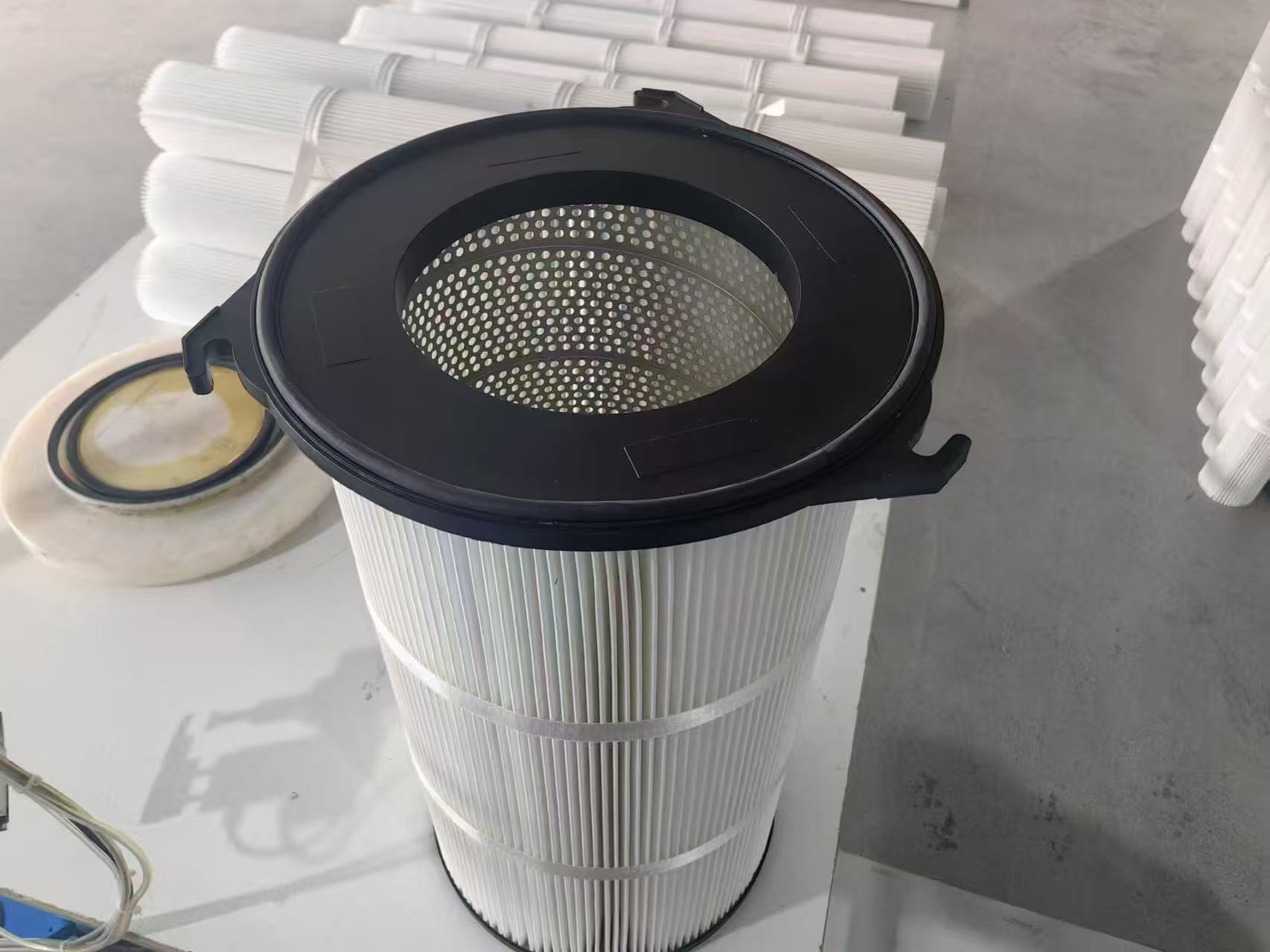


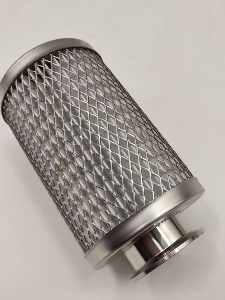
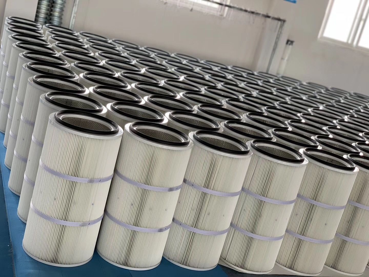
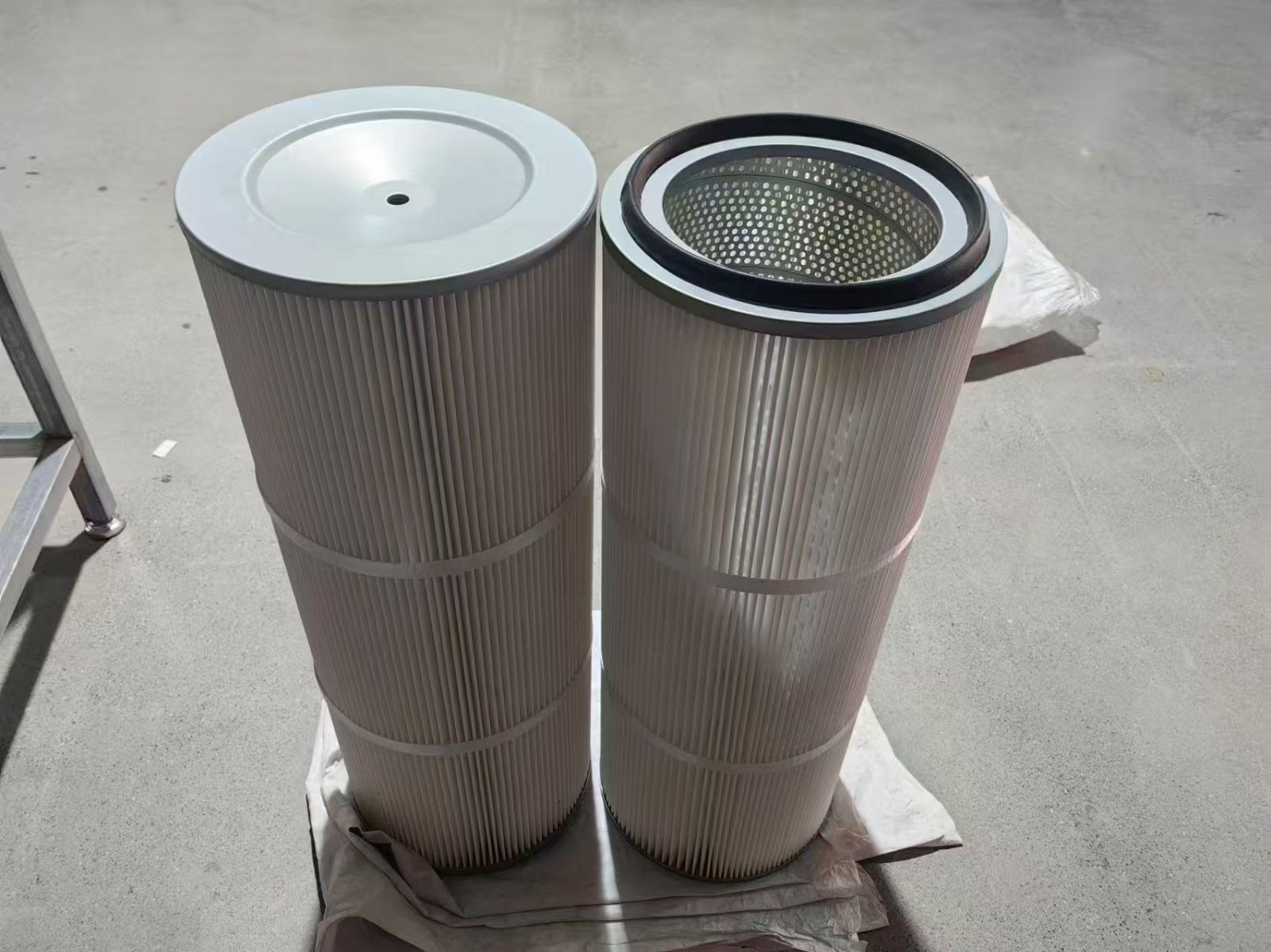
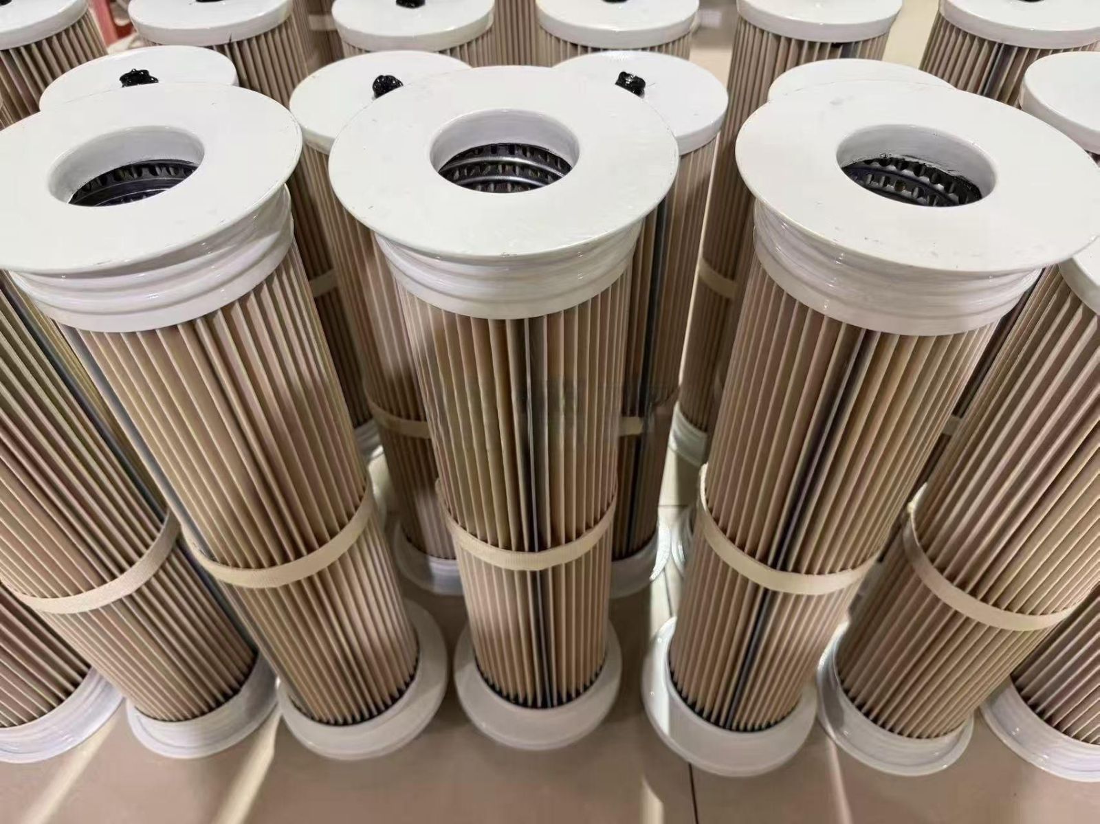
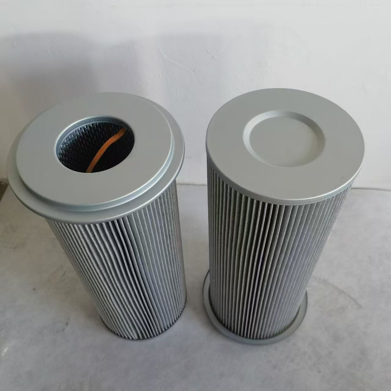
I break the problem down into fundamental fluid dynamics units rather than relying on empirical formulas:
Inlet Flow-Straightening Structure:
Design of flow-directing baffle angles to prevent direct impingement on the filter media (optimal range: 30°–45°)
Mathematical relationship between the expansion ratio of bell-mouth inlets and airflow uniformity
Internal Flow Field of Filter Cartridges:
Quantitative relationship between cartridge spacing and cross-flow interference
Control of flow velocity gradients along the vertical axis of the cartridges (top velocity ≤ 1.2 times bottom velocity)
Outlet Air Collection Structure:
Analysis of the resistance difference between conical and straight-cylinder outlets (conical structures can reduce local resistance by 15%–20%)
Matching principles for outlet velocity and the ducting system (outlet velocity should be ≤ 0.8 times the main duct velocity)
II. Core Elements of Resistance Balancing: Full-Chain Control from Filter Media to System
Focusing on the fundamental source of resistance—energy loss—rather than relying on traditional empirical selection methods:
Inherent resistance of the filter media:
Quantitative formulas relating fiber diameter and porosity to initial resistance (Initial Resistance = K × Media Thickness / Porosity²)
Dual impact of membrane coating on resistance (initial resistance increases by 10%–15%, but post-cleaning resistance drops by 30%)
Dynamic resistance during operation:
Exponential relationship between dust layer thickness and resistance (resistance increases quadratically with dust layer thickness)
Balancing strategy for cleaning frequency and resistance fluctuations (setting the differential between upper and lower resistance limits to ≤200 Pa)
System-level resistance matching:
Precise matching of filter cartridge resistance with fan pressure (total cartridge resistance should account for 60%–70% of fan pressure)
Proportional control of ductwork resistance relative to cartridge resistance (ductwork resistance ≤ 30% of cartridge resistance)III. Collaborative Design Method for Airflow Distribution and Resistance Balancing
Treating the two core elements as an interacting system rather than independent variables:
III. Collaborative Design Method for Airflow Distribution and Resistance Balancing
Treating the two core elements as an interacting system rather than independent variables:
Simulation-led approach:
Key parameter settings for Computational Fluid Dynamics (CFD) simulations (mesh resolution, turbulence model selection)
Optimization of filter cartridge layout and flow-guiding structures via flow field visualization
Dynamic adjustment mechanisms:
Automatic adjustment system for variable-angle flow deflectors (adjusting angles based on real-time airflow distribution)
Zonal cleaning strategy (increasing cleaning frequency for areas with uneven airflow)
Standardized testing procedures:
Airflow uniformity test method (utilizing multi-point air velocity measurement; a coefficient of variation ≤ 0.15 constitutes a pass)
Resistance balancing verification criteria (resistance differential between individual filter cartridges ≤ 50 Pa)
IV. Common Design Pitfalls and Solutions
Applying first-principles thinking to correct errors rooted in industry empiricism:
Pitfall 1: Maximizing the number of filter cartridges (ignoring airflow distribution, leading to overloading of peripheral cartridges)
Solution: Determine the optimal number of cartridges based on airflow uniformity rather than simply calculating based on airflow volume.
Pitfall 2: Excessively lowering initial resistance (resulting in overly large filter media pores and reduced filtration precision)
Solution: Employ a "gradient filtration" design—featuring coarse outer pores and fine inner pores—to balance resistance and precision.
Pitfall 3: Using fixed pulse-cleaning parameters (ignoring resistance fluctuations caused by changing operating conditions)
Solution: Install resistance sensors to enable dynamic adjustment of pulse-cleaning parameters.