

 Sdn Bhd")


Frequency: 20Hz-2MHz
Electric Level: 5mV-20V/50uA-100mA
DC Bias Current Source 0+/-40V, 0+/-100mA
Linux OS
LCR Function Optional
Features
�� The test speed is as high as 1800 times/s (>10kHz), without relay action time
�� Test level up to 20Vrms
�� The bias voltage is built-in ±40V/±100mA/2A
�� Up to 288 test pins (only TH2840NX)
�� Industry-friendly user experience: Linux bottom layer, built-in help file
�� 10.1 inch 1280×800 capacitive touch screen
�� Graphical pin association setting page, so that wiring is no longer a problem
�� Lk setting does not need to input the leakage inductance pin, which is more intuitive
�� Enhanced balance scanning function, from 5 points to 10 points
�� Range switching adopts electronic switch, fast speed, long life, no noise
�� Optional LCR function
�� Approximately 100M setting file storage space in the machine, and massive U disk setting file storage capacity
�� Provide host computer to support early model file format conversion to ensure compatibility
Applications
�� Switching transformer scanning test, comprehensive characteristics analysis.
�� Network transformer scanning test, comprehensive characteristics analysis
�� Discrete passive components (L, R, C) multi-channel scanning test
�� Relay drive line package, contact resistance multi-channel scanning test
�� Multi-channel DC resistance DCR scanning test
�� Comprehensive test analysis of multiple passive components in impedance network
Specifications
| Model | TH2840AX | TH2840BX | TH2840NX | |
| Display | Display | 10.1'' Captive Touch Screen | ||
| Ratio | 16:09 | |||
| Resolution | 1280×RGB×800 | |||
| Test PIN | 20PIN(By TH1806) | 48PIN(Can extend to 288PIN) | ||
| Frequency | Range | 20Hz-500kHz | 20Hz-2MHz | 20Hz-500kHz |
| Accuracy | 0.01% | |||
| Resolution | 0.1mHz (20.0000Hz-99.9999Hz) | |||
| 1mHz (100.000Hz-999.999Hz) | ||||
| 10mHz (1.00000kHz-9.99999kHz) | ||||
| 100mHz (10.0000kHz-99.9999kHz) | ||||
| 1Hz (100.000kHz-999.999kHz ) | ||||
| 10Hz (1.00000MHz-2.00000MHz) | ||||
| AC test signal mode | Rated value (ALC OFF) | Set the voltage as the Hcur voltage when the test terminal is open | ||
| Set the current to be the current flowing from Hcur when the test terminal is short-circuited | ||||
| Constant value (ALC ON) | Keep the voltage on the DUT the same as the set value | |||
| Keep the current on the DUT the same as the set value | ||||
| Test Level | AC Voltage | 5mVrms-20Vrms | F<=1MHz 5mVrms-20Vrms | 5mVrms-20Vrms |
| F>1MHz 5mVrms-15Vrms | ||||
| Accuracy | ±(10%×the set value+2mV)(AC<=2Vrms) | |||
| ±(10%×the set value+5mV)(AC��2Vrms) | ||||
| Resolution | 1mVrms (5mVrms-0.2Vrms) | |||
| 1mVrms (0.2Vrms-0.5Vrms) | ||||
| 1mVrms (0.5Vrms-1Vrms) | ||||
| 10mVrms (1Vrms-2Vrms) | ||||
| 10mVrms (2Vrms-5Vrms) | ||||
| 10mVrms (5Vrms-10Vrms) | ||||
| 10mVrms (10Vrms-20Vrms) | ||||
| AC Current | 50μArms-100mArms | |||
| Resolution(100Ω Internal Resistance) |
10μArms (50μArms-2mArms) | |||
| 10μArms (2mArms-5mArms) | ||||
| 10μArms (5mArms-10mArms) | ||||
| 100μArms (10mArms-20mArms) | ||||
| 100μArms (20mArms-50mArms) | ||||
| 100μArms (50mArms-100mArms) | ||||
| RDC Test | Voltage | 100mV-20V | ||
| Resolution | 1mV (0V-1V) | |||
| 10mV (1V-20V) | ||||
| Current | 0mA-100mA | |||
| Resolution | 10μA (0mA-10mA) | |||
| 100μA (10mA-100mA) | ||||
| DC Bias * | Voltage | 0V-±40V | ||
| Accuracy | AC<=2V 1%×the set voltage+5mV | |||
| AC>2V 2%×the set voltage+8mV | ||||
| Resolution | 1mV (0V - ±1V) | |||
| 10mV (±1V - ±40V) | ||||
| Current | 0mA-±100mA | |||
| Resolution | 10μA (0mA-10mA) | |||
| 100μA (10mA-100mA) | ||||
| Built-in current source | Current | 0mA-2A | ||
| Accuracy | I>5mA ±(2%×the set value+2mA) | |||
| Resolution | 1mA | |||
| Output impedance | 30Ω, ±4%@1kHz | |||
| 100Ω, ±2%@1kHz | ||||
| LCR Function | ||||
| Test Parameter | Method | Arbitrary selection of four parameters | ||
| AC | Cp/Cs, Lp/Ls, Rp/Rs, Z, Y, R, X, G, B, θ, D, Q, VAC, IAC | |||
| DC | RDC, VDC, IDC | |||
| Test Terminal Configuration | Four Terminal Pair | |||
| Test Cable Length | 0m | |||
| Computation | The absolute deviation from the nominal value Δ, the percentage deviation from the nominal value Δ% | |||
| Equivalent Way | Series, Parallel | |||
| Calibration Function | OPEN, SHORT, LOAD | |||
| Average Times | 1-255 | |||
| Range Selection | AUTO, HOLD | |||
| Range Configuration | LCR | 100mΩ, 1Ω, 10Ω, 20Ω, 50Ω, 100Ω, 200Ω, 500Ω, 1kΩ, 2kΩ, 5kΩ, 10kΩ, 20kΩ, 50kΩ, 100kΩ | ||
| RDC | 1Ω, 10Ω, 20Ω, 50Ω, 100Ω, 200Ω, 500Ω, 1kΩ, 2kΩ, 5kΩ, 10kΩ, 20kΩ, 50kΩ, 100kΩ | |||
| Test Speed (ms) | Fast+: 1ms. Fast: 3.3ms. Middle: 90ms. | |||
| Slow: 220ms | ||||
| Highest accuracy | 0.05% Please refer to the manuals for the details | |||
| Measurement display range | ||||
| Cs, Cp | 0.00001pF-9.99999F | |||
| Ls, Lp | 0.00001μH-99.9999kH | |||
| D | 0.00001-9.99999 | |||
| Q | 0.00001-99999.9 | |||
| R, Rs, Rp, X, Z, RDC | 0.001mΩ-99.9999MΩ | |||
| G, B, Y | 0.00001μs-99.9999S | |||
| VDC | ±0V-±999.999V | |||
| IDC | ±0A-±999.999A | |||
| θr | -6.28318 | |||
| θd | -179.999°-179.999° | |||
| Δ% | ±(0.000%-999.9%) | |||
| TurnsRatio | 1��0.001—1000��1 | |||
| Transformer Test | ||||
| Test Parameter | Cs/Cp, Ls/Lp, DCR, Zx, Rs/Rp, D, Q, dZ, , Lk, Phase, Balance Turns-Ratio, Ns:Np=U2/U1, Np:Ns=U1/U2 Turns: Ns=Np×U2/U1, Np=Ns×U1/U2 |
|||
| Test Mode | Continous | In the single trigger mode, manually trigger once, and once test all the test parameters. | ||
| Step | In the single trigger mode, manually trigger once to measure one parameter. Trigger again to measure the next parameter. | |||
| Test Speed (ms) | Fast | Fast: 3.3ms, Fast+ 0.56ms(>10kHz) | ||
| Middle | Middle: 90ms | |||
| Slow | Slow: 220ms | |||
| Bias Resource | See * | |||
| Average Times | Each test parameter can set different average times, the average times is 0-255 | |||
| Time Delay | Each test parameter can set a different delay time | |||
| Transformer Scanning | ||||
| Built in Scanning Board | No | One Board as standard. Could extend to six boards. ((24×2)PIN per board) | ||
| Transformer Handler | PIN Definition | NS1-NS30, GOOD, NG, TEST, TRIGGER, RESET | NS1-NS9, GOOD, NG, TEST, TRIGGER, RESET | |
| Output characteristics | Optocoupler isolation, ULN2003 drive enhancement, collector output | |||
| Model | Direct reading, percentage | |||
| Test Range | Auto, Hold | |||
| Bias Resource | See * | |||
| External scanning box | compatible to TH1901 series, TH1831 scanning box, TH1806 series | |||
| Number of windings | Primary | 60 | ||
| Secondary | 9 | |||
| Average Times | Each test parameter can set different average times, the average times is 0-255 | |||
| Time Delay | Each test parameter can set a different delay time | |||
| Test Speed (ms) | Fast | Fast: 3.3ms(>=1kHz). Fast+ : 0.56ms(>=10kHz) (Exclude the time for the realy action) | ||
| Middle | Middle: 90ms | |||
| Slow | Slow: 220ms | |||
| Test lead interface | 25*2pin FRC socket | |||
| Other Functions and specifications | ||||
| Storage | Internal | About 100M non-volatile memory test setting file | ||
| U Disk | Test setting file, screenshot graph, record file | |||
| Keyboard Lock | The front panel keys can be locked | |||
| Interface | USB HOST | 2 USB HOST ports. Mouse and keyboard could work at the same time. Only one U disk can be used at the same time. | ||
| USB DEVICE | Universal serial bus socket, small type B (4 contact positions); compatible with USB TMC-USB488 and USB2.0, the female connector is used to connect an external controller. | |||
| LAN | 10/100M Ethernet adaptive, 8 Pin | |||
| HANDLER | Used for Bin signal output | |||
| External DC BIAS Control | Support TH1778A (do not support transformer scanning) | |||
| RS232C | Standard 9-pin, cross | |||
| RS485 | Can accept modification or connect to RS232 to RS485 adaptor | |||
| Power-on Warm-up Time | 60 Minutes | |||
| Output Voltage | 100-120VAC/198-242VAC Optional, 47-63Hz | |||
| Power Consumption | More than 130VA | |||
| Size (WxHxD) mm | 430mm(W)x177mm(H)x265mm(D) | 430mm(W)x177mm(H)x405mm(D) | ||
| Weight (kg) | 11kg | 17kg | ||
Accessary
| Standard | ||||||
| Accessories name | Model | |||||
| Kelvin test lead with box four-terminal insulation and lock | TH26011BS | 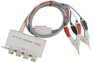 |
||||
| Connection Cable | TH26058A |  |
||||
| Test line at both ends | TH26004B | 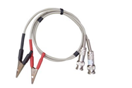 |
||||
| Manual transformer scan test fixture | TH1806B |  |
||||
| Foot switch | TH1801-001 |  |
||||

 BR 9626
  VN 3707
  US 3405
  IN 2400
  MY 1856
  SG 1614
  AR 1548
  CN 1471
