


Electronic Ballast Schematic Diagram
Due to different manufacturers, the design, manufacturing process, and quality of electronic ballasts vary from brand to brand. The following schematic diagram is commonly seen in daily life.

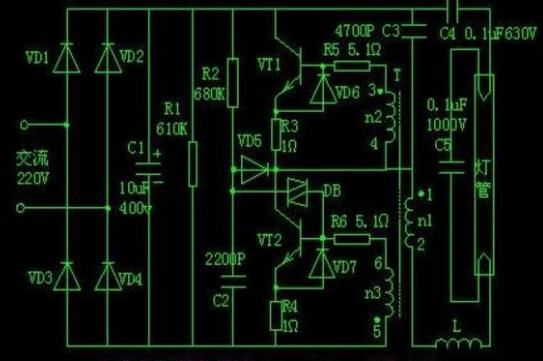
This electronic ballast is a bidirectional diode-based, series push-pull switching oscillator circuit. The switching transistors are two high-power plastic-encapsulated transistors (DK55). In the diagram, four small plastic-encapsulated transistors (VD1-VD4, commonly IN4007) form a bridge rectifier circuit. After the AC mains power is rectified by a bridge rectifier, a 208V DC voltage is obtained across the filter electrolytic capacitor C1. This voltage is applied between the emitter (E) terminals of VT1 and VT2. Simultaneously, this DC voltage charges capacitor C2 through resistor R1. When the voltage across C2 rises to the breakover voltage (16V-25V) of the DB3 bidirectional diode, the bidirectional diode is triggered and conducts, outputting a sawtooth pulse trigger voltage. This trigger pulse voltage is applied to the base of VT2, turning VT2 on. At this time, the 280V DC voltage across C1 forms a circuit through the DC blocking capacitor C4, the upper filament of the fluorescent tube, the series resonant capacitor C5, the lower filament of the fluorescent tube, the ballast inductor L, the n1 winding of the resonant transformer, and the emitter/emitter terminals of transistor VT2, beginning to charge C4 and C5. Because the n2 and n3 windings of the resonant transformer T are out of phase, VT2 is forward biased and conducts, while VT1 is reverse biased and cut off. When the charging of C4 and C5 ends, the current in the circuit decreases.
When the circuit current reaches zero (when the capacitor is fully discharged, the current in the circuit does not stop but continues to flow in its original direction due to the self-induction of the coil), that is, the polarity of the induced electromotive forces of n2 and n3 reverses. Under the action of positive feedback, the circuit flips, and VT1 becomes on and VT2 becomes off. The electrical energy stored in capacitors C4 and C5 discharges through the collector-exit terminal of VT1. The circuit consists of the collector terminal of VT1, the DC blocking capacitor C4, the upper filament of the fluorescent tube, the series resonant capacitor C5, the lower filament of the tube, the ballast inductor L, the n1 winding of the oscillating transformer, and the emitter terminal of transistor VT1. After C4 and C5 have discharged completely, the circuit returns to its initial oscillation state. VT2 becomes on again and VT1 becomes off again, and C4 and C5 begin to charge again, forming a self-excited oscillation. Its oscillation frequency depends on the capacitance of C5 and the inductance of L (the frequency of the oscillating circuit depends on the resonant frequency of the resonant circuit).
The ballast's initial oscillation frequency is 30-40kHz. VT1 and VT2 alternately conduct to provide high-frequency oscillation energy to the fluorescent tube. The fluorescent tube's filament is connected in series in the oscillation circuit. In the initial stage of circuit oscillation, the filament receives preheating energy. Before the tube is lit, capacitor C5 and inductor L form a series resonant circuit. During oscillation, the high-frequency high voltage output of the oscillation circuit is applied to the series resonant circuit. When the circuit reaches resonance, the voltage across the ballast inductor L and the resonant capacitor is higher than the voltage applied to the series resonant circuit, reaching over 300 volts. This high-frequency high voltage applied to the tube causes it to ignite rapidly. After the tube is lit, its internal resistance decreases. Because the tube is connected in parallel across the resonant capacitor C5, the Q value of the series resonant circuit drops rapidly as the fluorescent tube is turned on and lit, disrupting the resonance (circuit detuning). The local oscillator frequency decreases from 30Hz to about 15Hz, and the voltage across the tube drops to about 100V. In this case, the unsaturated leakage flux ballast inductor L only serves as a ballast, maintaining the lamp's ignition.
Advantages of Electronic Ballasts Compared to Traditional Inductive Ballasts
Replacing traditional inductive ballasts with electronic ballasts is an important measure in green lighting projects. Electronic ballasts offer the following advantages over inductive ballasts:
1. High Power Factor: Power factor (cosΦ) is a crucial indicator of power generation efficiency. A lower cosΦ results in greater reactive current and lower actual power supplied to the user. Ordinary inductive ballasts have a cosΦ of around 0.5, while electronic ballasts can reach 0.96, almost doubling the energy utilization rate compared to inductive ballasts. At the same output power, the power generation capacity can be halved.
2. High Luminous Efficiency: Because electronic ballasts use high-frequency excitation, the luminous efficiency of fluorescent lamps is significantly higher than when using inductive ballasts. Generally, electronic ballasts achieve 68.9 Lm/W, while inductive ballasts only reach 50 Lm/W.
3. Flicker-free: Fluorescent lamps powered by inductive ballasts flicker at 50Hz, severely affecting the eyesight of workers. Electronic ballasts, however, operate at ultra-high frequencies (the range audible to the human ear is 20Hz-20kHz), producing no noise and improving environmental comfort.
4. No noise: Because inductive ballasts have an iron core, improper manufacturing can cause a 50Hz AC buzzing sound, which is harsh. Electronic ballasts, operating at ultra-high frequencies, eliminate this flicker effect.
5. Fast and reliable starting: Inductive ballasts use bimetallic strips for starting, which can lead to contact sparking and poor contact. They are also often affected by temperature and grid voltage. In winter, low temperatures make it difficult for the starter to trip, and during peak electricity consumption periods when grid voltage is low, starting is also difficult. Therefore, repeated starting and flickering of fluorescent lamps causes premature damage to the filaments due to frequent impacts. Electronic ballasts, on the other hand, use high frequency and high voltage to induce glow discharge in the gas, allowing the lamp to ignite even at -25°C and a low voltage of 120V, and providing a quick and reliable start-up in one go.
6. Small size and light weight: Because electronic ballasts lack an iron core and coil, their weight is only one-tenth that of inductive ballasts; their smaller size also contributes to the overall lightweight design of the lighting fixture.
7. Significant energy savings: An inductive ballast for a 40W fluorescent lamp consumes approximately 8-9W due to iron and copper losses in the core and coil accounting for 30% of the total power. In contrast, an electronic ballast consumes only 1-2W. Combined with the increased luminous efficiency of fluorescent materials operating at high frequencies, using an electronic ballast can save users approximately 30% on energy. Based on a 30% energy saving, a 40W fluorescent lamp lit for 6 hours a day can save 0.09 kWh per day. The annual energy savings can recover the investment of 20 yuan, and the higher investment compared to an inductive ballast can be recovered after one year.
Advantages of Electronic Ballasts over Inductive Ballasts:
1. Energy Saving: All ballasts consume energy, but electronic ballasts consume less energy when driving the same lamp tube compared to inductive ballasts.
Electronic ballasts drive lamp tubes at frequencies up to 20kHz, resulting in a 10% higher luminous efficiency compared to inductive ballasts driving at 100Hz. In practice, this means that for the same light output, electronic ballasts can output less power to fluorescent lamps.
2. Instant Ignition: When you turn on a fluorescent lamp, it often flickers a few times before igniting.
However, fluorescent lamps driven by electronic ballasts, due to the greater energy released during startup, ignite instantly without flickering. A significant use of electronic ballasts is to provide a sufficient starting voltage to the two ends of the lamp, enabling it to ignite successfully on the first attempt.
Inductive ballasts require multiple attempts to light the lamp because they cannot provide a sufficient starting voltage to the fluorescent lamp in one go. Simultaneously, insufficient lamp current during the starting process leads to inadequate filament heating, filament powder sputtering, causing blackening at the ends of the lamp and shortening its lifespan.
3. Low-temperature and low-voltage starting:A 230V electronic ballast can start a lamp at voltages as low as 160V or even lower, while an inductive ballast requires at least 200V.
Electronic ballasts can also light lamps at temperatures as low as -20°C, a characteristic ideal for colder regions or harsh winters.
4. Good light quality:Energy-saving lamps driven by inductive ballasts flicker at 100Hz, which may be imperceptible to adults, but can be quite harmful to the eyes of children, especially infants. However, energy-saving lamps driven by electronic ballasts flicker at frequencies as high as 20,000 to 40,000 Hz, far exceeding the sensitivity range of an infant's eyes, and are therefore harmless. Inductive ballasts produce flicker, which can easily cause visual fatigue when working or studying in such an environment. It can also create illusions around rapidly rotating objects, posing a safety hazard. Using electronic ballasts eliminates flicker, protects eyesight, and is why commercially available student eye-protection lamps are designed and manufactured using electronic ballasts paired with tri-phosphor fluorescent tubes. High-performance electronic ballasts are flicker-free, noiseless, and protect the eyes and brain. When used with tri-phosphor fluorescent tubes, they offer excellent color rendering, realistic colors, high luminous efficacy, low light decay, and comfortable lighting; they purify the working, studying, and living environment; improve work efficiency; and benefit patient recovery; they are especially suitable for wards, examination rooms, and other places with high color rendering requirements.
5. Safety: Inductive ballasts rely on generating rapid high voltage to drive the lamp. When the lamp becomes difficult to start, the inductive ballast will continue to attempt to light it, generating a large amount of heat and posing a fire hazard. Ballast overheating is one of the leading causes of fires worldwide. Due to superior design and unique internal characteristics (fewer components, faster heat dissipation, etc.) and low power consumption during operation, electronic ballasts generate less heat and do not produce excessive heat. Good electronic ballasts meet EMC requirements, do not cause electromagnetic interference to the surrounding environment, and have strong anti-interference capabilities.
6. Long Lamp Lifespan: When an inductive ballast is used with a fluorescent lamp, the lamp current varies with the mains voltage. When the mains voltage is low, the lamp current also decreases. This decrease in lamp current leads to insufficient filament heating, filament powder sputtering, blackening at the lamp ends, and a shortened lamp lifespan. When the power supply voltage is too high, the lamp current also increases. Excessive lamp current will cause premature depletion of the filament electron powder and phosphor, shortening the lamp's lifespan.
Another use of electronic ballasts is to provide a suitable and stable current to the lamp's terminals after it is lit. As we know, the lifespan of a fluorescent lamp depends on the emission capability of the cathode, and the current crest factor (CF) is a crucial factor affecting the cathode's emission capability and stability. National standards stipulate a CF of less than or equal to 1.7. A higher CF results in greater lamp damage, faster blackening, and a shorter lifespan, while also causing flickering. Only good electronic ballasts can achieve the nationally specified CF range.
7. High Power Factor: Compared to inductive ballasts, electronic ballasts have a higher power factor (electronic ballast: PF = 0.95; inductive ballast: PF = 0.4). Therefore, electronic ballasts have less negative impact on the power supply system and result in less line loss.
8. Simple Installation: Electronic ballasts only require connecting two input wires and two pairs of output wires to the lamp tube. No starter is needed, significantly reducing usage and maintenance costs.
9. No Noise: During startup, electronic ballasts are noiseless, while inductive ballasts produce a loud humming sound that can interfere with the environment. Inductive ballasts emit a low-frequency noise of 50Hz, which can easily cause irritability. Electronic ballasts should be used in ENT listening rooms when using fluorescent lighting to prevent misdiagnosis; inductive ballasts are not recommended for use in wards and waiting areas when using fluorescent lighting, mainly due to flicker and noise that can cause discomfort to patients. Classrooms and living rooms should use electronic ballasts to achieve a better living and learning environment.
- Lightweight: An inductive ballast weighs up to 700 grams, while the Auglan electronic ballast weighs only 120 grams.

 BR 17498
  US 6037
  VN 5159
  AR 2741
  MY 2367
  IQ 1991
  MX 1762
  SG 1595
