1. Driver Circuit
Poor driver circuit performance can, at best, cause the power transistor to malfunction or, at worst, damage it. Its characteristics are a key factor in determining the current rise rate and dynamic saturation voltage drop. Increasing the base drive current increases the current rise rate, reducing the saturation voltage drop of the power transistor, thereby minimizing turn-on losses. Excessive drive current can cause the power transistor to oversaturate, resulting in a longer exit-saturation time, which is detrimental to the switching process and minimizing turn-off losses. Whether the driver circuit has a fast protection function is a key factor in determining whether a power transistor will be damaged after an overvoltage or overcurrent event.
There are many types of driver circuits for power transistors. The following describes a driver circuit for a discrete power transistor, as shown in Figure 1. The circuit consists of two components: electrical isolation and a transistor amplifier circuit. Diode VD2 and potential compensation diode VD3 form a Baker clamp anti-saturation circuit, which keeps the power transistor in a critical saturation state when conducting. Under light load, if all the emitter current from V5 is injected into V, V will oversaturate, prolonging the desaturation time during shutdown. With the Baker clamp, when V oversaturates and the collector potential falls below the base potential, VD2 automatically turns on, allowing excess drive current to flow into the collector, maintaining Ubc ≈ 0. This ensures that V remains in critical saturation when conducting. C2 in the figure is a capacitor that accelerates the turn-on process. During turn-on, R5 is short-circuited by C2. This reduces the overshoot of the drive current and increases the steepness of the leading edge, accelerating turn-on. In addition, when V5 is turned on, C2 is charged with a positive polarity on the left and a negative polarity on the right, preparing for the power transistor to turn off. When V5 is turned off and V6 is turned on, the charged voltage on C2 applies a reverse voltage to the emitter junction of the V tube, causing the power transistor to turn off quickly.
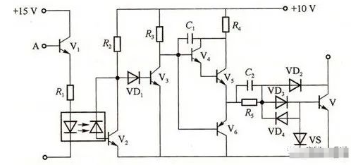
Figure 1. Driving circuit for discrete power transistors
2. Protection circuit
(1) Overcurrent and short-circuit protection
Because power transistors have problems such as secondary breakdown, and secondary breakdown is very fast, far less than the melting time of fast fuses, overcurrent protection methods such as fast fuses are useless for power electronic devices such as power transistors.
Overcurrent protection for power transistors depends on the driver and special protection circuits.
(a) Voltage state recognition protection
When a power transistor is in an overload or short-circuit fault state, as the collector current increases sharply, its base-emitter voltage and collector-emitter voltage change accordingly. This characteristic can be used to protect the power transistor from overload and short-circuit. The circuit diagram is shown in Figure 2.
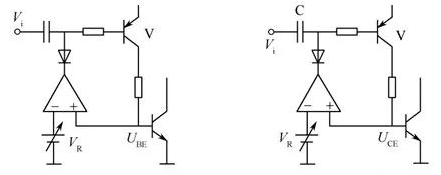
Figure 2 Voltage identification protection circuit
(b) Bridge arm interlock protection
When the inverter is running, a bridge arm short circuit fault may occur, causing device damage. Only after confirming that one power transistor in the same bridge arm is turned off can the other power transistor be turned on. This can prevent the two transistors from being turned on at the same time and avoid bridge arm short circuit.
The thermal capacity of the power transistor is extremely small and the overcurrent capability is very low. It is required that the fault detection, signal transmission and protection action can be completed instantly, and the current must be limited to the overload capability limit within the microsecond time.
(2) Undersaturation and oversaturation protection
The secondary breakdown of the power transistor is mostly caused by the power transistor operating in an oversaturated state, and the oversaturation caused by the over-base drive makes the storage time of the power transistor unnecessarily prolonged, which directly affects the switching frequency of the power transistor. Therefore, the oversaturation and undersaturation protection of the power transistor plays an extremely important role in its safe and reliable operation. Usually, the undersaturation protection can be completed by automatically adjusting the size of the base drive current according to the base-emitter voltage drop of the driven power transistor to form a quasi-saturated base driver.
The above is an introduction to the drive and protection of the power transistor. Power transistors share a similar structure, operating principle, and characteristics to conventional bipolar transistors. They are three-terminal devices consisting of three semiconductor layers and two PN junctions. They come in two types: PNP and NPN. However, NPN is the most common type of power transistor currently.