F001 Main contactor checkback If a main contactor checkback is configured, no checkback takes place within the time set in P600 after the power-up command. In the case of externally excited synchronous motors (P095 = 12), there is no checkback for the excitation current unit. P591 Src Contactor Msg Parameter value must be in conformance with the connection of the main contactor checkback. Check the checkback loop of the main contactor (or the checkback of the excitation current unit in the case of synchronous motors). F002 Pre-charging When pre-charging, the minimum DC link voltage (P071 Line Volts × 1.34) of 80 % has not been reached. The maximum pre-charging time of 3 seconds has been exceeded. Check the supply voltage, Compare with P071 Line Volts (compare P071 with the DC link voltage on DC units). Check the rectifier/regenerative unit on DC units. The rectifier/regenerative unit must be switched on before the inverter is switched on. Faults Faults and Alarms Vector Control Chassis Type Frequency Converter 476 869 4070 76 J AB-74 Siemens AG 11-2 Operating Instructions SIMOVERT MASTERDRIVES Fault number Fault Counter-measure F006 DC link overvoltage Shutdown has occurred due to excessive DC link voltage. Line voltage I DC voltage I Shutdown I range I threshold 200 V - 230 V I 270 V – 310 V I appr. 410 V 380 V - 480 V I 510 V – 650 V I appr. 820 V 500 V - 600 V I 675 V – 810 V I appr. 1020 V 660 V - 690 V I 890 V – 930 V I appr. 1220 V Check the supply voltage or input DC voltage. Converter is operating in regenerative mode without rectifier possibility. If the converter supply voltage is at the upper tolerance limit and it is operating at full load, F006 can also be caused by a line phase failure. Possibly: • Increase P464 Decel Time, • Activate P515 DC Bus Volts Reg (check P071 beforehand) • Reduce P526 Fly Search Speed. • Reduce P259 Max Regen Power (only for P100 = 3, 4 or 5) For parallel-connected converters (BF L) r949 = 1: Overvoltage in the DC link of the master r949 = 2: Overvoltage in the DC link of the slave. F008 DC link undervoltage The lower limit value of 76 % of the DC link voltage (P071 Line Volts), or of 61 % when kinetic buffering has been enabled, has been fallen short of. Undervoltage in the DC link in ’normal’ operation (i.e. no SIMULATION). Undervoltage in the DC link with active kinetic buffering and speed less than 10 % of the rated motor speed. It was a ’brief power failure’ which was not detected until system recovery (auto restart flag). Check: • Input DC voltage • DC link F011 Overcurrent Overcurrent shutdown has occurred. The shutdown threshold has been exceeded. Check • the converter output for short-circuit or ground fault • the load for an overload condition • whether motor and converter are correctly matched • whether the dynamic requirements are too high. F012 I too low During excitation of the induction motor, the current did not rise above 12.5 % of the setpoint magnetizing current for no-load operation. Only for closed loop n/f/T control (P100 = 3, 4 or 5) If no motor is connected, go into the simulation mode P372. Check current detection, check power section. Vector Control Chassis Type Frequency Converter Faults and Alarms SIEMENS AG 476 869 4070 76 J AB-74 SIMOVERT MASTERDRIVES Operating Instructions 11-3 Fault number Fault Counter-measure F015 Motor stall Motor has stalled or is locked: • if the static load is too high • if the acceleration or deceleration time is too fast or if load change is too fast and too great, • due to incorrect parameterization of the pulse encoder pulse number P151 or of the analog tachometer scaling P138. • due to disturbed speed signals (tachometer shield not connected) The fault is only generated after the time set in P805. The binector B0156 is set, in the status word 2 r553 Bit28. To detect whether the drive is locked, see P792 (Perm Deviation) and P794. With n/f control, this fault is tripped if the torque limits have been reached (B0234). With speed control (P100 = 4) and master drive (see P587), the fault can also point to an interruption in the encoder cable. This case has the same significance as if the drive is locked. With v/f control, the I(max) controller has to be activated (P331). The monitor does not operate with v/f textile applications (P100 = 2). Motor has stalled or is locked: • By reaching the maximum frequency in the case of synchronous motors (P095 = 12,13) As a result of missing or excessively high excitation current in the case of externally excited synchronous motors (P095 = 12): (flux is too small or too great). When the maximum frequency (including control reserves) (B0254) has been reached on synchronous motors, the fault is generated immediately. If the deviations in the rotor flux are too great, first of all, the converter current is switched to zero, the excitation current is reduced and, after some time, the fault message is tripped at the level of the double damping time constant (2*r124.1). During this wait time, the status word bit is set already B0156 (r553.28) • Reduce load • Release brake • Increase current limits • Increase P805 PullOut/BlckTime • Increase P792 response threshold for set/actual deviation Only for f/n/T control (P100 = 3, 4, 5) • Increase torque limits or torque setpoint Only n/T control or v/f control with speed controller: (P100 = 0, 4, 5) • Check tachometer cable breal • Check pulse encoder pulse number • Check analog tachometer scaling • Connect shield of tachometer cable on motor side and converter side • Reduce smoothing of speed pre-control P216 (only n/T control) Only frequency control: (P100 = 3) • Slow down acceleration time (see also P467-ProtRampGen Gain) • Increase current in the lower frequency range (P278, P279, P280) • Switch in speed controller pre-control (P471>0) • Set EMF controller more dynamically (P315) to max. approx. 2 • Increase changeover frequency for the EMF model (P313) • Replace by speed control with pulse encoder In the case of overmodulated n/f controller: • Track speed setpoint with the speed actual value so that the set/actual deviation is always less than that set in P792. Only for synchronous motor: (P095 = 12) • Check current limits of the excitation unit. • Check excitation current setpoint and actual value (incl. wiring) • Check voltage limits of the excitation unit during dynamic current changes. • Check drive system for resonance oscillations. Faults and Alarms Vector Control Chassis Type Frequency Converter 476 869 4070 76 J AB-74 Siemens AG 11-4 Operating Instructions SIMOVERT MASTERDRIVES Fault number Fault Counter-measure F017 SAFE OFF in operation Check whether the switch for SAFE OFF (X009/5-6) is open (only for devices with Order No....-11, ...-21,...-31,...-61). F018 F set fly The found set-frequency could not be implemented because the additional setpoint is too high. Check additional setpoint. Power up after coasting. Release both directions of rotation. F019 Motor not found Motor has not been found (during flying restart without tachometer). Power up after coasting. Possibly increase P525 Fly Search Amps. F020 Motor temperature The motor temperature limit value has been exceeded. r949 = 1 Limit value of motor temperature exceeded r949 = 2 Short-circuit in the cable to the motor temperature sensor or sensor defective r949 = 3 wire break in the cable to the motor temperature sensor or sensor defective Check the motor (load, ventilation, etc.). The actual motor temperature can be read in r009. Check P381 Mot Tmp Fault Check the KTY84 input at connector X103:29,30 for short-circuit. F021 Motor I2t Parameterizable limit value of the I2t monitoring for the motor has been exceeded. Check: P383 Mot Tmp T1 F023 Inverter temperature The limit value of the inverter temperature has been exceeded. r949 = 1: Limit value of inverter temperature has been exceeded. r949 = 2: Sensor 1: Wire break of sensor cable or sensor defective r949 = 18: Sensor 2: Wire break of sensor cable or sensor defective r949 = 34: Sensor 3: Wire break of sensor cable or sensor defective r949 = 50: Sensor 4: Wire break of sensor cable or sensor defective Measure the air intake and ambient temperature. Please observe the reduction curves at ϑ >40 ºC. Check: • Whether the fan -E1 is connected and is rotating in the correct direction. • That the air entry and discharge openings are not restricted. • Temperature sensor at -X30 F025 UCE Ph. L1 There has been an UCE shutdown in phase L1. Check: • Phase L1 for short-circuit or ground fault (-X2:U2 – including motor). • That CU is correctly inserted. • That the switch for ‘SAFE OFF’ (X9/5-6) is open (only for units with Order No. ...-11, ...-21,...-31,...-61). Vector Control Chassis Type Frequency Converter Faults and Alarms SIEMENS AG 476 869 4070 76 J AB-74 SIMOVERT MASTERDRIVES Operating Instructions 11-5 Fault number Fault Counter-measure F026 UCE Ph. L2 There has been an UCE shutdown in phase L2. Check: • Phase L2 for short-circuit or ground fault (-X2:V2 – including motor). • That CU is correctly inserted. • That the switch for ‘SAFE OFF’ (X9/5-6) is open (only for units with Order No. ...-11, ...-21,...-31,...-61). F027 UCE Ph. L3 There has been an UCE shutdown in phase L3. Check : • Phase L3 for short-circuit or ground fault (-X2:W2 – including motor). • That CU is correctly inserted. • That the switch for ‘SAFE OFF’ (X9/5-6) is open (only for units with Order No. ...-11, ...-21,...-31,...-61). F028 Supply phase The frequency and the amplitude of the DC link ripple indicate a single-phase power failure. Check the supply voltage. F029 Meas. value sensing A fault has occurred in the measured value sensing system; • (r949 = 1) Offset adjustment not possible in phase L1 • (r949 = 2) Offset adjustment not possible in phase L3 • (r949 = 3) Offset adjustment not possible in phases L1 and L3 • (r949=65) Autom. Adjustment of the analog inputs is not possible Fault in measured value sensing. Fault in power section (valve cannot block) Fault on CU F035 Ext. fault 1 Parameterizable external fault input 1 has been activated Check: • whether there is an external fault • whether the cable to the appropriate digital input has been interrupted • P575 Src No ExtFault1 F036 Ext. fault 2 Parameterizable external fault input 2 has been activated Check: • Whether there is an external fault • Whether the cable to the appropriate digital input has been interrupted • P586 Src No ExtFault2 Faults and Alarms Vector Control Chassis Type Frequency Converter 476 869 4070 76 J AB-74 Siemens AG 11-6 Operating Instructions SIMOVERT MASTERDRIVES Fault number Fault Counter-measure F037 Analog input Check the connection to • Analog input 1 -X102:15, 16. • Analog input 2 -X102: 17, 18. Check parameters • P632 CU AnaIn Conf • P634 CU AnaIn Smooth • P631 CU AnaIn Offset F038 Voltage OFF during parameter storage During a parameter task, a voltage failure occurred on the board. Re-enter the parameter. The number of the parameter concerned can be seen in fault value r949. F040 AS internal Incorrect operating status Replace CU (-A10) F041 EEPROM fault A fault has occurred when storing the values in the EEPROM. Replace CU (-A10) F042 Calculating time Calculating time problems Reduce the calculating time load: • Increase P357 Sampling Time • Calculate individual blocks in a slower sampling time Observe r829 CalcTimeHdroom. F044 BICO Manager F045 Opt. Board HW A hardware fault has occurred when accessing an optional board. Replace CU Check connection of the board subrack to the boards F046 Par. Task Power the unit down and up again. Replace CU (-A10). F047 Internal calculating time The calculating time in the gating unit computer is not sufficient. Replace CU (-A10). For synchronous motors (P095 = 12): Pulse frequency is set too high (P340 > 2kHz). F048 Internal pulse frequency Change P340 Pulse Frequency. F049 SW Version The firmware versions on the CU have a different firmware release. Use uniform firmware F050 TSY Init. Error when initializing the TSY board Check: • Whether the TSY is correctly inserted Vector Control Chassis Type Frequency Converter Faults and Alarms SIEMENS AG 476 869 4070 76 J AB-74 SIMOVERT MASTERDRIVES Operating Instructions 11-7 Fault number Fault Counter-measure F051 Speed encoder Digital tachometer or analog tachometer sensing are faulty. Check the parameters: • P130 Src SpdActV • P151 • P138 AnalogTachScale • P109 Motor #PolePairs The product of P109 and P138 must be smaller than 19200. Check or replace tachometer. Check connection to tachometer. Replace CU F052 n-Cntr. Input The fault input on the TSY has been active. Cancel tachometer with control track P130 Src Spd ActV Replace TSY. Check the tachometer connection at the TSY. Several versions are possible, depending on the type of tachometer. F053 Tachometer dn/dt The permissible change value of the speed encoder signal P215 dn(act,perm) has been doubly exceeded. Check tachometer cables for interruptions. Check earthing of tachometer shield. • The shield must be connected both at the motor and the converter side. • The encoder cable must not be interrupted. • The encoder cable must not be laid together with the power cables. • Only recommended encoders should be used. • In the case of a signal fault, the DT1 board may have to be used. If necessary, change P215 F054 Sensor board initialization fault Fault value r949 1: Board code incorrect 2: TSY not compatible 20: TSY board double F056 SIMOLINK telegram failure Check: • Fiber-optic cable ring • Whether an SLB in the ring is without voltage • Whether an SLB in the ring is faulty • Check P741 (SLB Tlg OFF) F058 Parameter error during parameter task No counter-measure Faults and Alarms Vector Control Chassis Type Frequency Converter 476 869 4070 76 J AB-74 Siemens AG 11-8 Operating Instructions SIMOVERT MASTERDRIVES Fault number Fault Counter-measure F059 Parameter error after factory setting/initialization The number of the inconsistent parameter is indicated in fault value r949. Correct this parameter (ALL indices) and power down and power up the voltage again. Depending on circumstances, several parameters may be concerned, i.e. repeat the procedure. F060 MLFB is missing This is set if the MLFB = 0 after exiting INITIALIZATION (0.0 kW). MLFB = order number. After acknowledgement, in INITIALIZATION enter a suitable MLFB in parameter P070 MLFB (6SE70..). (Only possible with the corresponding access stages to both access parameters). F061 Incorrect parameterization A parameter entered during drive setting (e.g. P107 Mot Rtd Freq, P108 Mot Rtd Speed, P340 Pulse Frequency) is not in a permissible range (depending on control type) Acknowledge the fault and change the corresponding parameter value. The missing parameter is indicated in r949 as a fault value. Vector Control Chassis Type Frequency Converter Faults and Alarms SIEMENS AG 476 869 4070 76 J AB-74 SIMOVERT MASTERDRIVES Operating Instructions 11-9 Fault number Fault Counter-measure F062 Multi-parallel circuit Fault in connection with the multi-parallel circuit or board ImP1 has been detected. r949 = 10: Communications card does not reply. When writing the control word, BUSY is not active if CSOUT is inactive. Communications card is probably not inserted. r949 = 11,12: Timeout during BUSY during initialization. BUSY does not become active within 1 sec. r949 = 15: Timeout during BUSY during normal communication. BUSY does not become active within 1 sec. r949 = 18: Timeout when reading out the fault information from the ImPIs. Within one second after activation of FAULT no fault cause can be supplied by the ImP1. r949 = 20+i: HW conflict. This is set if bit HWCONF is set in status word of slave i. (Fault in the configuration of the multi-parallel circuit) r949 = 30+i: HW version of ImPI is not compatible. The relevant slave number is contained in i. r949 = 40: Number of slaves does not tally with the setpoint number of slaves of the unit. r949 = 50+i: Inconsistency in the number of slaves. The number of slaves notified by the ImPI is not in conformance with the number of status words or with the setpoint number of slaves of the MLFB. Counter-measure: • Check ImPI or communications card and replace, if necessary. • Check configuration of multi-parallel circuit. • Check parameterization. • Replace CU. • Replace ImPI. F065 SCom Telegram No telegram was received at an SCom interface (SCom/USS protocol) within the telegram failure time. r949 = 1 SCom1 r949 = 2 SCom2 • Check the connection CU -X100:1 to 5 and check the connection PMU -X300. • Check “Scom/SCB TLG OFF“ P704.01 (SCom1) and P704.02 (SCom2) • Replace CU (-A10). Faults and Alarms Vector Control Chassis Type Frequency Converter 476 869 4070 76 J AB-74 Siemens AG 11-10 Operating Instructions SIMOVERT MASTERDRIVES Fault number Fault Counter-measure F070 SCB Init. Error during initialization of the SCB r949 = 1: Board code incorrect r949 = 2: SCB board not compatible r949 = 5: Initialization data error • Check parameter SCB Protocol P696 parameter and Scom/SCB Baud Rate P701.03 r949 = 6: Timeout during initalization r949 = 7: SCB board double r949 = 10: Error in configuration channel F072 EB initialization error r949 = 2: 1. EB1 not compatible r949 = 3: 2. EB1 not compatible r949 = 4: 1. EB2 not compatible r949 = 5: 2. EB2 not compatible r949 = 21: There are three EB1 boards r949 = 22: There are three EB2 boards F073 AnaIn1 SL1 4 mA at analog input 1, slave1 fallen short of Check the connection between the signal source and the SCl1 (Slave 1) -X428:4, 5. F074 AnaIn2 SL1 4 mA at analog input 2, slave1 fallen short of Check the connection between the signal source and the SCI1 (Slave 2) -X428:7, 8. F075 AnaIn3 SL1 4 mA at analog input 3, slave1 fallen short of Check the connection between the signal source and the SCI1 (Slave 3) -X428:10, 11. F076 AnaIn1 SL2 4 mA at analog input 1, slave2 fallen short of Check the connection between the signal source and the SCI1 (Slave1) -X428:4, 5. F077 AnaIn2 SL2 4 mA at analog input 2, slave2 fallen short of Check connection between signal source and SCI1 (Slave 2) -X428:7,8. F078 AnaIn3 SL2 4 mA at analog input 3, slave2 fallen short of Check connection between signal source and SCI1 (Slave 3) -X428:10, 11. F079 SCB Telegram No telegram has been received by the SCB (USS, Peer-to-Peer, SCI) within the telegram failure time. • Check connection of SCB1(2). • Check P704.03“SCom/SCB TLG OFF“. • Replace SCB1(2). • Replace CU (-A10). Vector Control Chassis Type Frequency Converter Faults and Alarms SIEMENS AG 476 869 4070 76 J AB-74 SIMOVERT MASTERDRIVES Operating Instructions 11-11 Fault number Fault Counter-measure F080 TB/CB Init. Error during initialization of the board at the DPR interface r949 = 1: TB/CB not inserted or TB/CB board code incorrect r949 = 2 TB not compatible r949 = 3: CB not compatible r949 = 5: Error in initialization data r949 = 6: Timeout during initialization r949 = 7: TB/CB board double r949 = 10: Error in configuration channel Check that the T300 / CB board is inserted correctly Check the CB initialization parameter: • P918 CB Bus Address • P711 to P721 CB parameters 1 to 11 F081 Opt. Board Heartb TB, CB or SCB no longer processes the monitoring counter r949 = 0: TB/CB Heartbeat counter r949 = 1: SCB Heartbeat counter • Replace SCB, TB or CB • Check connection between subrack and optional boards F082 TB/CB Tlg No new process data have been received by the TB or the CB within the telegram failure time. r949 = 1: TB/CB r949 = 2: 2. CB • Check the connections of the CB/TB. • Check P722 “CB/TB TLG OFF“. • Replace CB or TB. F087 SIMOLINK initialization fault • Replace CU • Replace SLB F090 MId Param. An error occurred when attempting to change a parameter from the standstill measurement or the rotating measurement (Mot ID). Power down and power up again. If it reoccurs, replace the CU. F091 MId Time The rotating measurement takes longer than programmed in a measured status. Possible causes: • Load torque too high • Load torque not uniform • Ramp-function generator disabled Eliminate the cause and re-start the measurement (power up the converter again). If it re-occurs, replace the CU. Faults and Alarms Vector Control Chassis Type Frequency Converter 476 869 4070 76 J AB-74 Siemens AG 11-12 Operating Instructions SIMOVERT MASTERDRIVES Fault number Fault Counter-measure F095 MId n(set) Due to entries for • Permissible phase sequence • Maximum frequency, • Minimum speed, • Changeover frequency between V and I model, • Start of field-weakening frequency, • Frequency suppression bandwidth It was not possible to determine a permissible frequency range for the rotating measurement. There must be a 10% frequency range which lies above 1.1 times the changeover frequency and below 0.9 times the start of field-weakening frequency. Possible counter-measures; • Permit both phase sequences • Increase maximum frequency • Reduce minimum speed, • Reduce changeover frequency between the V and I model. • Reduce or remove the frequency suppression bandwidth. F096 MId abort The rotating measurement was aborted due to inadmissible external intervention. The fault value in r949 defines the type of intervention: 4 Setpoint inhibit 5 Changeover, setpoint channel 8 Unexpected change in the converter status 12 Motor data set changeover (for function selection "Compl. Mot ID“) 13 Changeover to slave drive 14 Motor data set changeover to data set with v/f_charac 15 Controller inhibit is set 16 Ramp-function generator is disabled 17 Selection "Tacho test" for F controller 18 Ramp-function generator stopped Eliminate cause F097 MId measured value The measured values for the nominal rampup time when optimizing the controller deviate too greatly. Cause: very unsteady load torque If necessary, increase the torque limit values to 100 percent Vector Control Chassis Type Frequency Converter Faults and Alarms SIEMENS AG 476 869 4070 76 J AB-74 SIMOVERT MASTERDRIVES Operating Instructions 11-13 Fault number Fault Counter-measure F098 MId Tachof The rotating measurement has detected a fault in the speed actual value signal. The fault value defines the type of fault. The fault message may have been erroneously generated if the drive speed is externally forced (e.g. completely locked drive generates the "no signal" message) The fault value in r949 defines the type of intervention 4 No speed signal present 5 Sign of the signal is incorrect 6 A track signal is missing 7 Incorrect gain 8 Incorrect pulse number Checking the measurement cables. Checking the parameters • P130 Src Speed ActV • P151 Encoder Pulse # F100 GRND Init During the ground fault test, a current not equal to zero has been measured, or an UCE or overcurrent monitoring has responded, although no valve has yet been triggered. The cause of the fault can be read out from r376 "GrdFltTestResult". Check the converter output for short-circuit or ground fault (-X2:U2, V2, W2 – including motor). Check that the CU is inserted correctly. Sizes 1 and 2: • Check the transistor modules on the PEU board -A23 for short-circuit. Size 3 and 4: • Check the transistor modules -A100, -A200, -A300 for short-circuit F101 GRND UCE During the ground fault test, the UCE monitoring has responded in a phase in which no valve has been triggered. Check valves in the power section for shortcircuit, and on converters with fiber-optic gating, check the gating unit wiring and the UCE checkbacks for correct assignment. r376 can be interrogated to indicate which UCE monitoring has responded. F102 GRND Phase During the ground fault test, a current flows in a phase in which no valve has been triggered or the UCE monitoring has responded in the phase in which the valve has been triggered. The fault value can be read out from r949. The digit of the xth position indicates the valve where the fault occurred at power-up x = 1 = V+ x = 2 = V- x = 3 =U+ x = 4 = U- x = 5 = W+ x = 6 =WThe figure of the xth digit indicates the phase in which I ≠ 0 and thus a valve must be defective (always conductive). x = 1 = Phase 1 (U) x = 3 = Phase 3 (W) x = 4 = Phase 1 (U) or 3 (W) Examine phase for defective valves (always conductive). Faults and Alarms Vector Control Chassis Type Frequency Converter 476 869 4070 76 J AB-74 Siemens AG 11-14 Operating Instructions SIMOVERT MASTERDRIVES Fault number Fault Counter-measure F103 Ground fault There is a ground fault or a fault in the power section. During the ground fault test, a current flows from the phase in which a valve has been triggered, the overcurrent comparator has responded, or a UCE monitoring has responded in a phase in which a valve has been triggered. Read out fault value from r949. The digit of the xth position indicates the valve where the fault occurred at power-up. x = 1 = V+ x = 2 = V- x = 3 =U+ x = 4 = U- x = 5 = W+ x = 6 =WCheck the motor including the feeder cable for short-circuit. If no ground fault is present, check the power section for defective valves (always conductive). The digit of the xth position indicates the phase in which I ≠ 0 and therefore a valve must be defective (always conductive). 1 = Current in phase 1 (U) 2 = UCE in phase 2 (V) 1) 3 = Current in phase 3 (W) 4 = Only overcurrent occurred The speed of the motor shaft during the ground fault test should be less than 10 % of the nominal speed! 1) A ground fault or a defective valve (aways conductive) is present in phase V or the switch for ‘SAFE OFF’ (X9/5-6) is open (only for units with Order No. ...-11, ...- 21,...-31). F107 MId I = 0 A fault has occurred during the test pulse measurement. Read out fault value from r949. The figures of the grey shaded areas indicate which fault has occurred. xx = 01: Both current actual values remain 0 xx = 02: Motor-converter cable phase U interrupted xx = 03: Motor-converter phase V interrupted xx = 04: Motor-converter phase W interrupted xx = 05: Current actual value I1 remains 0 xx = 06: Current actual value I3 remains 0 xx = 07: Valve U+ does not trigger xx = 08: Valve U- does not trigger xx = 09: Valve V+ does not trigger xx = 10: Valve V- does not trigger xx = 11: Valve W+ does not trigger xx = 12: Valve W- does not trigger xx = 13: Sign I1 incorrect xx = 14: Sign I3 incorrect xx = 15: Sign I1 and I3 incorrect xx = 16: I1 confused with I3 xx = 17: I1 confused with I3 and both currents have an incorrect sign The digit of the grey shaded area indicates where the fault has occurred. Vector Control Chassis Type Frequency Converter Faults and Alarms SIEMENS AG 476 869 4070 76 J AB-74 SIMOVERT MASTERDRIVES Operating Instructions 11-15 Fault number Fault Counter-measure x = 0 = Single converter x = 1 = Inverter 1 x = 2 = Inverter 2 x = 3 = Inverters 1 and 2 Check that all 3 motor feeder cables and the motor windings do not have any interruption. Check the connection between the current converter and the electronics and check the current converter itself. Check the correct input of the rating plate data for the motor data set valid during the measurement. F108 MId Unsym During the DC measurement, the measurement results for the individual phases differ significantly. The fault value indicates which quantity(ies) is (are) concerned and in which phase the greatest deviation occurred. Read out fault value from r949. The digit of the xth position indicates; Transverse voltage too high x = 1 = phase R; x = 2=phase S; x = 3 = phase T Dev. stator resistance (1, 2, 3 as above) Dev. rotor resistance (1, 2, 3 as above) Dev. dead-time compensation (1, 2, 3 as above) Deviation valve voltage (1, 2, 3 as above) The motor, power section or actual-value sensing are significantly non-symmetrical. F109 MId R(L) The rotor resistance determined during DC measurement deviates too significantly from the value which was calculated by the automatic parameterization from the rated slip. • Incorrect input of rated speed or rated frequency • Pole pair number incorrect F110 MId di/dt During test pulse measurement, the current has increased significantly faster than was expected. Thus for the 1st test pulse, an overcurrent condition occurred within the first half of the minimum switch-on time. • There may be a short-circuit between two converter outputs. • The motor rating plate data have not been correctly parameterized. • The motor leakage is too low. F111 Fault e_Func A fault has occurred while calculating the equalization function. F112 Unsym l_sigma The individual leakage test results deviate too significantly. Faults and Alarms Vector Control Chassis Type Frequency Converter 476 869 4070 76 J AB-74 Siemens AG 11-16 Operating Instructions SIMOVERT MASTERDRIVES Fault number Fault Counter-measure F114 MId OFF The converter has automatically aborted the automatic measurement as the time limit was exceeded up to converter power-up, or due to an OFF command during the measurement; the selection in P115 Function Select is reset. For P115 Function Select = 2 restart "Motor data identification at standstill". The ON command must be provided within 20 s after the alarm message A078 = standstill measurement appears. Withdraw the OFF command, and restart the measurement. F115 KF internal Power-down the converter and electronics and power-up again. F148 Fault 1 Function blocks Check cause of fault, see function diagram 710 F149 Fault 2 Function blocks Check cause of fault, see function diagram 710 F150 Fault 3 Function blocks Check cause of fault, see function diagram 710 F151 Fault 4 Function blocks Check cause of fult, see function diagram 710 F243 Link int. Faults in internal linking. One of the two linked partners does not reply. Replace CU (-A10). F244 ParaLink int. Fault in the internal parameter linking Release comparison of MWH software and CU software regarding the transfer parameters. Replace CU (-A10). F255 Fault in the EEPROM Switch off the unit and power it up again. If it occurs again, replace the CU.
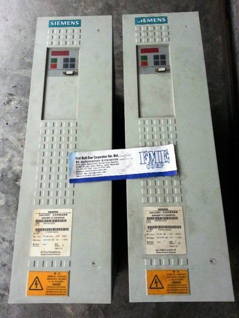
6SE7031-0EE60-1AA0
6SE7031-2EF60-1AA0
6SE7031-5EF60-1AA0
6SE7031-8EF60-1AA0
6SE7032-1EG60-1AA0
6SE7032-6EG60-1AA0
6SE7033-2EG60-1AA0
6SE7033-7EG60-1AA0
Main Office
First Multi Ever Corporation Sdn Bhd (791306-P)
47G & 51G, Jalan Bestari 5/5G, Taman Nusa Bestari, 81300 Skudai, Johor, Malaysia.


 US 1348
  MY 1153
  CN 134
  KR 93
KR 93  AU 70
AU 70  DE 61
DE 61  AP 60
AP 60  SG 50
SG 50 
